IPRO7AI Reef EVK V4.0
V4.0
The IPRO7AI Reef EVK is built around an IPRO7AI (QFN56) with its flash and PSRAM inside the chip package. The board carries an OV5640 camera connector, a PDM digital microphone, a headset jack and a speaker amplifier, a microSD socket, an RGB LED, keys, and a 40-pin expansion header in the same position and pin order as on a Raspberry Pi. It is powered from USB-C only and has no LCD and no battery. This page covers the V4.0 board (silkscreen "IPRO7AI REEF EVK V4.0"); every step on this site is written for it.
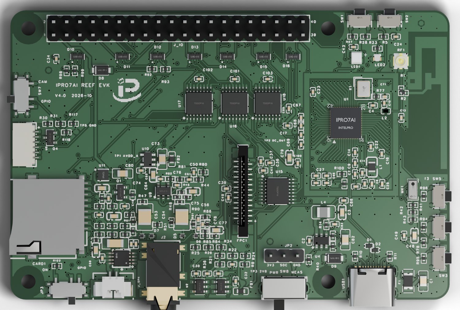
On-board features
| Block | Contents |
|---|---|
| Core | IPRO7AI (U1, QFN56): RISC-V RV32IMAFC, NPU, ISP, 2.4 GHz radio (BLE, IEEE 802.15.4); 32 MHz crystal (X1) |
| Memory | 2 MB flash and 8 MB PSRAM in the package; 256 KB OCRAM on the chip |
| Antenna | PCB antenna E1 (default); move the 0 Ω resistor from R2 to R1 to use the u.FL connector RF1 instead |
| Camera | FPC1: 24-pin, 0.5 mm pitch vertical FPC connector with the OV5640 FLEX-24 pinout, 8-bit DVP; the camera's 2.8 V and 1.5 V come from on-board regulators |
| Camera / GPIO switch | SW7 routes the 16 camera pins to J_IO through four SN74CB3Q3257 switches; in the GPIO position the camera supply is off |
| Audio in | PDM digital microphone MK1; headset microphone from jack J2 into analog inputs AIN6 and AIN7 |
| Audio out | The IPRO7AI GPDAC drives the headphone stage (TLV9061) to jack J2 (3.5 mm, CTIA), and the PAM8302A class-D amplifier to the speaker connector J_SPK (1.25 mm, 2 pins, for an 8 Ω speaker) |
| Storage | microSD socket CARD1 (push-push), 4-bit SD interface; card detect and socket power each on a GPIO |
| USB | USB-C (USB1): 5 V power and USB 2.0 Full-Speed device |
| Debug | U6: 6-pin, 1.0 mm pitch (SH1.0) with the console UART, BOOT and RESET; connects to the IPRO Debug Probe |
| Keys and LEDs | SW1 BOOT, SW2 RESET, user keys SW3 / SW4 / SW5 (side-actuated); LED1 RGB LED (WS2812B-2020), LED2 power LED (green) |
| Expansion | J_IO: 2 × 20, 2.54 mm header in the same position and pin order as the Raspberry Pi 40-pin header; all signals are 3.3 V |
| Current measurement | SW8 (PWR / MEAS) and JP2 measure the IPRO7AI's 3.3 V current |
| Size | 85 × 56 mm, 1.6 mm thick, six layers; four Ø2.75 mm mounting holes on a 58 × 49 mm pitch, placed relative to the 40-pin header as on a Raspberry Pi, for M2.5 standoffs |
Specifications follow the V4.0 design files (schematic and bill of materials).
Switches and jumpers
| Ref | Position | Function |
|---|---|---|
| SW7 | CAM (default) | Camera pins go to the IPRO7AI and the camera supply is on. Keep it on CAM whenever you use the camera |
| GPIO | The 16 camera pins go to J_IO (the pins marked * in the header table); both camera regulators are off | |
| SW8 | PWR | Normal use: the IPRO7AI's 3.3 V comes straight from the board supply |
| MEAS | Measurement: the IPRO7AI's 3.3 V comes through JP2, which must carry an ammeter or an external 3.3 V supply | |
| JP3 | ON | The microSD socket is always powered |
| GPIO | GPIO14 switches the socket supply: on while low or undriven, off while high | |
| JP2 | — | 3 pins: 1 = 3V3 (board 3.3 V), 2 = SOC (the IPRO7AI's 3.3 V), 3 = GND; used only with SW8 on MEAS |
To measure the IPRO7AI's current, unplug USB-C, connect an ammeter between JP2 pins 1 and 2 (or an external 3.3 V supply across pins 2 and 3), slide SW8 to MEAS, then plug USB-C back in. When you are done, unplug USB-C, slide SW8 back to PWR and only then remove the ammeter. The reading covers the IPRO7AI's 3.3 V pins with their decoupling capacitors and the boot-strap pull-ups, not the peripherals.
Before power-on
- Power the board from USB-C only. The 5 V pins on J_IO (pins 2 and 4) are outputs; you cannot power the board through them.
- All I/O is at 3.3 V; do not connect 5 V signals.
- Unplug USB-C before you connect or disconnect the camera cable.
- Leave SW8 on PWR. With SW8 on MEAS, do not plug in USB-C unless JP2 carries an ammeter or an external 3.3 V supply: the IPRO7AI would be unpowered while the peripherals' 3.3 V back-feeds it through the I/O pins.
Quick start
At the end the board runs the out-of-box firmware ipro7ai_reef_demo and answers reef selftest on its console. The host needs the RISC-V toolchain (from INTELPRO), IntelProCube 0.7.0.1 (from GitHub), CMake 3.15 or later, GNU make and Python 3.8 or later; see Get Started.
-
Set the switches and connect: slide SW7 to CAM and SW8 to PWR. Connect the console cable to U6: a 3.3 V USB-to-UART cable (pinout under Debug connector U6), or the IPRO Debug Probe through a pin-reversed cable. Plug in USB-C last.
The green power LED, LED2, lights up. U6 does not power the board; only USB-C does.
-
Find the serial port: list the serial ports on the host.
A USB-to-UART cable shows up as one port, for example
/dev/cu.usbserial-XXXX. The IPRO Debug Probe shows up as two (device nameIPRO7 CMSIS_DAP): the one ending in02is the Reef console, the one ending in04the CCI bridge. On Windows, look up theCOMnumber in Device Manager. -
Build the out-of-box firmware from the SDK root:
The build ends with the flash and RAM usage; the image is
apps/platform/ipro7ai_reef_demo/build/build_out/ipro7ai_reef_demo_IPRO7.bin. -
Enter download mode: hold SW1 (BOOT), press and release SW2 (RESET), then release SW1.
The console goes silent. Other ways are under Download mode. With an IPRO Debug Probe you can skip this step: IntelProCube 0.7.0.1 puts the chip in download mode through the probe and resets it after flashing.
-
Flash from the IntelProCube directory (
./ipro_iot_tool_linuxon Linux,ipro_iot_tool.exeon Windows):./ipro_iot_tool_macos --chipname ipro7 --chip-variant IPRO7AI \ --port /dev/cu.usbserial-XXXX --baudrate 921600 \ --pt chips/ipro7/partition/partition_cfg_2M.toml \ --firmware <SDK>/apps/platform/ipro7ai_reef_demo/build/build_out/ipro7ai_reef_demo_IPRO7.binFlashing worked only if the output ends with
[All Success]; the tool exits 0 even when it fails.--chip-variant IPRO7AIselects the flash pins of the QFN56. -
Start and self-test: press SW2, open the console at 115200 baud (8N1, no flow control) and type
reef selftest.The boot log shows
IPRO7AI Reef carrier demoandshell ready - ..., and the RGB LED breathes blue once. Within about 3 secondsreef selftestprints:[1/4] RGB LED: red, green, blue [2/4] speaker: 1 kHz, 300 ms, 20% [3/4] SD slot: empty, supply on [4/4] camera bus: OV5640 at 0x3C done - keys: press any and run `btn status`Line 3 depends on whether a card is inserted; without a camera line 4 reads
no sensor. SW3, SW4, SW5 and SW1 light the LED red, green, blue and white.
Once you know the steps, build_freertos.sh builds, flashes and opens the console in one go. It picks --chip-variant IPRO7AI from the application's configuration and opens the console at the application's own baud rate. With SDK firmware already running it sends reboot_dl first; for the very first flash, enter download mode with the keys:
export IPRO_FLASH_TOOL=<ICUBE>/ipro_iot_tool_macos
./build_freertos.sh -p /dev/cu.usbserial-XXXX \
    -P <ICUBE>/chips/ipro7/partition/partition_cfg_2M.toml \
    build flash monitor ipro7ai_reef_demo
The script cannot write boot2 or an mfg payload: flash the first ipro_ble_remote image and ipro_reef_teach with IntelProCube directly. Options are listed under Tool Command Lines.
Download mode
To be flashed, the IPRO7AI has to see BOOT (GPIO41) high when it comes out of reset; it then enters the ROM's download mode. In download mode the console is silent. After flashing, press SW2 to boot normally.
| Method | How | When |
|---|---|---|
| Keys | Hold SW1 (BOOT), press and release SW2 (RESET), release SW1 | Always, including when the firmware does not respond |
| Console command | Type reboot_dl at the console |
While SDK firmware runs; build_freertos.sh flash sends it for you |
| Auto-download cable | U6 pin 5 (BOOT) and pin 6 (RESET) reach the IPRO7AI through 1 kΩ each; wire them to the DTR and RTS lines of a USB-to-UART cable so the host can drive them | With a cable that brings out DTR and RTS |
| IPRO Debug Probe | Write IPRODL_1, then IPRORST_RESET to the probe port ending in 02; after flashing write IPRODL_0, then IPRORST_RESET |
With the IPRO Debug Probe |
Enter download mode through the Debug Probe (one keyword per line):
python3 tools/serial_monitor.py /dev/cu.usbmodemXXXX02 --send IPRODL_1 --timeout 1
python3 tools/serial_monitor.py /dev/cu.usbmodemXXXX02 --send IPRORST_RESET --timeout 1
After flashing, send IPRODL_0 and IPRORST_RESET the same way and the board boots normally.
Images that use boot2 (for example the Reef build of ipro_ble_remote) also have reboot_usb [code]: it restarts into boot2's USB download mode (waiting indefinitely by default). boot2 also stops in this USB rescue mode when an OTA package fails its check.
Out-of-box firmware ipro7ai_reef_demo
Each block on the board has its own group of shell commands; help lists them all. The Reef has no LCD, so the camera is checked from the shell.
| Block | Shell commands | What they do |
|---|---|---|
| Status and self-test | reef status, reef selftest |
State of the pins, keys, LED, amplifier and detect lines; one-shot self-test |
| RGB LED | led <r> <g> <b>, led rainbow, led off |
Set a color (0–255) or a rainbow effect |
| Keys | btn status, btn watch |
Debounced state and press counts; live press / release events |
| Speaker and headset | spk tone <hz> <ms>, hp |
Sine wave from the GPDAC; adding hp to a command mutes the amplifier so only the headset plays. hp on its own reads the headset detect (GPIO26) |
| Audio input | mic rec <source> <s>, mic play, mic loop |
Source pdm (on-board microphone) or headset; records at 16 kHz into PSRAM (up to 10 s) for playback, or monitors live |
| Recording to SD | mic sdrec <source> <name> <s> |
Writes sd:/rec/<name>.wav |
| USB microphone | mic usb <source> |
The board becomes a 16 kHz USB microphone on USB-C |
| SD card | sd mount, sd ls, sd test, sd bench, sd power |
FatFS mounted at sd:; write, read back and verify; with JP3 on GPIO, sd power switches the socket supply through GPIO14 |
| FIN card | fin, fin cycle |
State of the IPRO6S FIN card in the socket; with JP3 on GPIO, power-cycles the card |
| Camera | cam probe, cam start, cam status, cam snap, cam bar on |
OV5640 in YUV422 1280×720 through ISP channel 0; frame, frame-rate and error counters, ASCII thumbnail, sensor color bars |
The AUX-IN input in the application's README (mic rec aux) belongs to the earlier carrier; V4.0 has no AUX-IN jack.
Camera bring-up order (SW7 on CAM):
cam probe        read the sensor ID over SCCB
cam start        start capture
cam status       run twice, one second apart: the frame count rises, the error count stays
cam bar on       switch to color bars
cam snap         the ASCII thumbnail shows vertical bands
cam bar off
cam snap         the real scene
Wi-Fi and RTSP camera stream
With the IPRO6S FIN card in the microSD socket, the Reef joins Wi-Fi over SDIO and serves an MJPEG stream of the camera over RTSP (rtsp://<ip>:8554/av0_0).
-
FIN card firmware: the IPRO6S application
ipro6_if_wifi, built withdefconfig_ipro6_sdio:make -C apps/platform/ipro6_if_wifi DEFCONFIG=defconfig_ipro6_sdio # build_ipro6_sdio/build_out/ipro6_if_wifi_IPRO6.binHow to update it is on the IPRO6S page; once the card is on Wi-Fi,
ipro6s_ota <http url>at the Reef console updates it. -
Reef firmware:
ipro7ai_reef_demowithdefconfig_wifi_ipro6s: -
Switches: put JP3 on GPIO so that
fin cyclecan power-cycle the card.
At the console type ipronet_up <ssid> <psk>, then rtsp_cam on, and open rtsp://<ip>:8554/av0_0 in an RTSP player. The full walkthrough is Wi-Fi and RTSP Camera Stream.
Supported examples
These 9 applications (11 configurations) build and run on the Reef; each has an example page with the flash and run steps. Apart from ipro7ai_reef_demo, ipro_reef_teach and ipro_agora_sentino, a plain make builds another board: add DEFCONFIG= for the Reef.
| Application | Build command (from the SDK root) | Console | Flashing notes |
|---|---|---|---|
ipro7ai_reef_demo |
make -C apps/platform/ipro7ai_reef_demo |
115200 | --pt chips/ipro7/partition/partition_cfg_2M.toml |
ipro7ai_reef_demo (Wi-Fi) |
make -C apps/platform/ipro7ai_reef_demo DEFCONFIG=defconfig_wifi_ipro6s |
115200 | Needs a FIN card running ipro6_if_wifi, JP3 on GPIO |
ipro_reef_teach |
make -C apps/ai/ipro_reef_teach |
115200 | Own table partition_reef_teach.toml, --skip-ota and --mfg; see Flash the Edge AI Firmware |
ipro_ble_remote |
make -C apps/bluetooth/ble/ipro_ble_remote DEFCONFIG=defconfig_reef |
115200 | The first flash needs --boot2 and partition_cfg_2M_remote_ab.toml; OTA only with this A/B table |
ipro_throughput_test |
make -C apps/bluetooth/ble/ipro_throughput_test DEFCONFIG=defconfig_reef |
115200 | Needs two boards |
ipro_le_audio_headset |
make -C apps/bluetooth/le_audio/ipro_le_audio_headset DEFCONFIG=defconfig_reef |
115200 | — |
ipro7_uvc_cam |
make -C apps/multimedia/ipro7_uvc_cam DEFCONFIG=defconfig_reef_ov5640 |
115200 | --pt chips/ipro7/partition/partition_cfg_2M.toml |
ipro7_uvc_cam (rock-paper-scissors) |
make -C apps/multimedia/ipro7_uvc_cam DEFCONFIG=defconfig_reef_rps |
115200 | As above; the model is linked into the firmware |
ipro7_jpeg_decode |
make -C apps/multimedia/ipro7_jpeg_decode DEFCONFIG=defconfig_reef |
921600 | — |
ipro_ai_link |
make -C apps/test/ipro_ai_link DEFCONFIG=defconfig_reef |
115200 | Needs a microSD card |
ipro_agora_sentino |
make -C apps/multimedia/ipro_agora_sentino |
115200 | Fetch the AOSL core first; needs a FIN card and a Sentino device triple |
A DEFCONFIG= build goes to build_<name>/build_out/, where the name is the file name without defconfig_: defconfig_reef builds into build_reef/.
USB identities
The Reef's USB-C carries the IPRO7AI's USB 2.0 Full-Speed device; what the host sees depends on the firmware. Every application uses VID 0x3896 (INTELPRO INC.).
| PID | Application and mode | What the host sees |
|---|---|---|
0x0705 |
ipro_reef_teach, image mode |
UVC camera + CDC serial port |
0x0720 |
ipro_reef_teach, voice mode |
CDC serial port |
0x0721 |
ipro_reef_teach, sensor mode |
CDC serial port |
0x0701 |
ipro7_uvc_cam |
UVC camera "IPRO7 UVC Cam" |
0x0704 |
ipro_ai_link |
Two CDC serial ports (data, console) |
0x0003 |
ipro7ai_reef_demo, mic usb |
USB audio device (microphone) |
ipro_ble_remote, ipro_throughput_test, ipro_le_audio_headset, ipro7_jpeg_decode, ipro_agora_sentino and the defconfig_wifi_ipro6s build of ipro7ai_reef_demo use no USB device; USB-C only powers the board.
Pin map
| Block | Pins |
|---|---|
| UART0 console | TX GPIO20, RX GPIO21 (U6 pins 3 / 4; J_IO pins 8 / 10) |
| USB device | D+ GPIO8, D− GPIO9 |
| Camera DVP | Data GPIO0–7, PCLK GPIO38, VSYNC GPIO39, HREF GPIO40, XCLK GPIO22 (driven by the IPRO7AI), RESETB GPIO34, PWDN GPIO35 |
| Camera SCCB | SIOC GPIO36, SIOD GPIO37 (I2C0; the pull-ups are on the camera module) |
| Speaker | GPDAC GPIO23 → PAM8302A; enable on GPIO25, high = on, off at power-up |
| Headset jack J2 | Headphones share GPDAC GPIO23 with the speaker; microphone on AIN6 (GPIO12) and AIN7 (GPIO13); plug detect on GPIO26 (GPADC) |
| PDM microphone | CLK GPIO16, DATA GPIO17 |
| RGB LED | WS2812B DI on GPIO24, driven from SPI0 MOSI (needs pin_swap_enable = 0) |
| Keys | SW1 BOOT GPIO41 (pulled down, high when pressed); SW3 GPIO10, SW4 GPIO27, SW5 GPIO11 (low when pressed) |
| microSD | CLK GPIO30, CMD GPIO31, DAT0 GPIO29, DAT1 GPIO28, DAT2 GPIO33, DAT3 GPIO32; card detect GPIO15; socket power GPIO14 (with JP3 on GPIO, low = on) |
| I2C on J_IO | SDA GPIO19, SCL GPIO18 (4.7 kΩ pull-ups on the board) |
The microSD CMD and DAT lines have no external pull-ups, so enable the IPRO7AI's internal pull-ups (the SDK board configuration does). Before you switch the socket off with GPIO14, drive GPIO28–33 low or make them inputs. These pins go to the socket only, not to J_IO.
40-pin expansion header J_IO
J_IO is a 2 × 20, 2.54 mm vertical header in the same position and pin order as the Raspberry Pi 40-pin header: power, ground, I2C and UART are where you expect them. Odd pins are in the inner row, even pins along the board edge. All signals are 3.3 V, and every signal pin has ESD protection.
- Pins marked * go through the camera switches: they reach the IPRO7AI only with SW7 on GPIO and carry no signal with SW7 on CAM.
- The 5 V on pins 2 and 4 is USB 5 V through a diode. It is present only while USB-C is plugged in, and you cannot power the board through it.
- Pins 16 and 18 (BOOT, RESET) are not connected by default; fit 0 Ω resistors at R92 and R93 if you need them.
- Pins 27 and 28 are a second I2C bus; with SW7 on GPIO you can use them to read an ID EEPROM on an add-on board.
| Pin | Signal | Notes | Pin | Signal | Notes |
|---|---|---|---|---|---|
| 1 | 3.3 V | Power output | 2 | 5 V | Output (USB 5 V through a diode) |
| 3 | GPIO19 | I2C SDA (4.7 kΩ pull-up) | 4 | 5 V | Output (same as pin 2) |
| 5 | GPIO18 | I2C SCL (4.7 kΩ pull-up) | 6 | GND | |
| 7 | GPIO27 | SW4 key | 8 | GPIO20 | UART0 TX (console) |
| 9 | GND | 10 | GPIO21 | UART0 RX (console) | |
| 11 | GPIO10 | SW3 key | 12 | GPIO0 * | |
| 13 | GPIO14 | microSD power control | 14 | GND | |
| 15 | GPIO15 | microSD card detect | 16 | BOOT | Not connected by default |
| 17 | 3.3 V | Power output | 18 | RESET | Not connected by default |
| 19 | GPIO4 * | 20 | GND | ||
| 21 | GPIO5 * | 22 | GPIO35 * | ||
| 23 | GPIO7 * | 24 | GPIO6 * | ||
| 25 | GND | 26 | GPIO34 * | ||
| 27 | GPIO37 * | Second I2C SDA | 28 | GPIO36 * | Second I2C SCL |
| 29 | GPIO22 * | 30 | GND | ||
| 31 | GPIO39 * | 32 | GPIO40 * | ||
| 33 | GPIO38 * | 34 | GND | ||
| 35 | GPIO1 * | 36 | GPIO11 | SW5 key | |
| 37 | NC | Not connected | 38 | GPIO3 * | |
| 39 | GND | 40 | GPIO2 * |
Debug connector U6
U6 is a 6-pin, 1.0 mm pitch right-angle connector (SH1.0) with the console UART and the BOOT and RESET lines, for flashing and for the boot log. The console is UART0, which is also the flashing UART: 115200 baud, 8N1, no flow control (921600 baud while flashing).
| Pin | Signal | Notes |
|---|---|---|
| 1 | NC | Not connected |
| 2 | GND | Ground |
| 3 | TX (GPIO20) | Reef output (console out) |
| 4 | RX (GPIO21) | Reef input (console in) |
| 5 | BOOT | To GPIO41 through 1 kΩ; high when reset is released = download mode |
| 6 | RESET | To the IPRO7AI reset pin through 1 kΩ; low = reset |
Connect the CN_UART connector of the IPRO Debug Probe to U6 with a cable whose pin order is reversed end to end: probe pin n goes to U6 pin 7 − n (probe RST to RESET, DL to BOOT, TXD to RX, RXD to TX, GND to GND, and the probe's 3V3 lands on the unconnected pin).
Cable direction
Do not use a straight cable (pin 1 to pin 1): the UART and control lines end up on the wrong pins, and the probe's 3.3 V on its pin 6 reaches RESET on U6.
SDK board support
- Board selection: the
.configsetsCONFIG_IPRO7AI_REEF=yandCONFIG_BOARD="IPRO7AI_REEF"; the pin definitions are inbsp/board/ipro7/ipro7ai_reef_board_config.h. Do not also setCONFIG_EVB=yin the same configuration: with both, the build targets the IPRO7 EVB. - PSRAM: the build does not apply Kconfig
select, so every Reef configuration statesCONFIG_USE_PSRAM=yexplicitly (except thedefconfig_reefofipro_throughput_test, which leaves PSRAM off). Start a new application from a copy ofapps/platform/ipro7ai_reef_demo/.config. - Pin definitions: the
BOARD_*pins for the console, USB, camera, speaker, microphones, LED, keys and SD card match this page. The comments in that file about the expansion header and jumpers describe the earlier (V3.0) carrier; for V4.0 this page is the reference. - Crystal trim: when the
.configdoes not setCONFIG_IPRO7_XTAL_CAPCODE, the build applies 95 for the Reef; set another value in.configto override it (0 keeps the value found at boot). The[XTAL] capcodeline in the boot log shows the value in use. - Flash layout: the Reef configurations of
ipro7ai_reef_demo,ipro7_uvc_cam,ipro7_jpeg_decodeandipro_throughput_testlink a 1 MB layout, which fits either in-package flash; the.configofipro_reef_teachandipro_agora_sentinoand thedefconfig_reefofipro_ble_remote,ipro_le_audio_headsetandipro_ai_linksetCONFIG_IPRO7_FLASH_2M=y. To give a 1 MB-layout application the whole 2 MB flash, addCONFIG_IPRO7_FLASH_2M=yto its configuration. - Zephyr RTOS: this release has no Zephyr board for the Reef. The SoC Kconfig notes that a Reef can run
ipro7_evbimages withCONFIG_SOC_IPRO7_XTAL_CAPCODE=95; that use is not validated.
Related documents
- IPRO AI Teach: teach this board to recognize images, voices and sensor signals with IPRO AI Studio.
- Examples: the applications that run on the Reef, each with build, flash and run steps.
- Pinout & Peripheral Mapping, Power & Current Measurement, IPRO7AI, IPRO6S.
apps/platform/ipro7ai_reef_demo/README.md: the out-of-box firmware's full command set and camera debugging notes.- IPRO7AI Reef development kit user guide (V4.0 board hardware, interfaces and power) and IPRO Debug Probe user guide: available from INTELPRO, see Documents.